
The Off-Grid Electrical Wiring Sequence and Why Order Prevents Fires
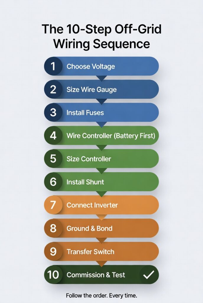
Building a safe off-grid electrical system requires following a specific wiring sequence because skipping steps or reversing the order destroys equipment and creates fire hazards. Ten steps in a specific order. Each step depends on the previous one being connected and configured first. Reversing even one step can destroy a $350 charge controller in 10 seconds or melt cable insulation at the battery terminal.
This article is the master map for the entire off-grid electrical wiring process. Each section summarizes a critical step and links to the full detailed guide for that step. A homeowner in Rockwood followed this exact sequence and built a $3,500 workshop system that worked on the first attempt. A DIYer in Milton reversed the sequence and destroyed $400 in equipment in under 2 minutes.
The difference between those two outcomes is not skill or experience. It is sequence. Follow these 10 steps in order and your off-grid electrical system will work on the first power-up. Skip a step or reverse the order and you risk fire, equipment damage, or both. For a broader overview of solar systems, see our solar generator Ontario guide.
System Voltage Selection and Wire Gauge as the Foundation of Every Build
Step 1 is choosing your system voltage. This single decision affects every other component in the off-grid electrical system. A 48V system allows thinner wire, smaller charge controllers, and lower overall cost compared to 12V. A 1,200W array at 12V needs 93.8A of conductor capacity. The same array at 48V needs only 23.4A. That difference saves $400 on copper wire alone on a typical 30-foot run. For the full voltage comparison, see our 12V vs 24V vs 48V guide.
Step 2 is selecting wire gauge based on distance, current, and the 3 percent voltage drop rule. Undersized wire wastes power as heat inside the conductor. A 30-foot run of 14 AWG carrying 20A loses 8 percent of the panel’s output to resistance. The same run in 10 AWG loses only 3 percent. Oversized wire costs more upfront but protects the system for 25 years. For the complete wire gauge calculation, see our wire gauge solar panels guide.
Off-Grid Electrical Circuit Protection and the Charge Controller Sequence
Step 3 is fusing every positive conductor. Every positive wire in the off-grid electrical system needs a fuse within 7 to 12 inches of the battery terminal. Class T fuses are the standard for lithium banks because they interrupt a short circuit in under 5 milliseconds. A short circuit on an unfused 48V lithium bank can deliver 500A or more, which melts wire insulation and ignites surrounding materials. A $15 fuse prevents a $15,000 house fire. For the complete fusing guide, see our solar system fusing guide.
Step 4 is wiring the charge controller in the correct sequence. Connect the battery to the controller first. Then connect the solar panels. The controller must see battery voltage before receiving panel power. If you connect panels first, the controller receives high voltage with no load to absorb the current. The capacitors overload and the controller releases smoke. Cold-weather VOC in Ontario must stay below the controller’s maximum input voltage. For the full wiring protocol, see our charge controller wiring guide. Step 5 is sizing the controller correctly. Array watts divided by battery voltage equals required controller amps. Add 25 percent headroom for edge-of-cloud irradiance spikes. A Victron MPPT 100/50 handles up to 700W at 12V or 2,400W at 48V. For the sizing formula with worked examples, see our charge controller sizing guide.
Battery Monitoring and Inverter Connection as the Power Delivery Layer
Step 6 is installing a Victron SmartShunt on the battery negative terminal. The shunt measures every amp-hour entering and leaving the battery and calculates true State of Charge using coulomb counting. The critical rule is that every negative wire in the off-grid electrical system must pass through the shunt. If any wire bypasses it, that current is invisible and the SoC reading drifts from reality. For the complete installation sequence, see our battery monitor shunt guide.
Step 7 is connecting the inverter to the battery. The inverter connects directly to the battery bank, not to the charge controller. The wire gauge must handle the full inverter output current. A 3,000W inverter at 12V draws 250A, requiring 4/0 AWG cable. At 48V the same inverter draws only 62.5A, requiring 4 AWG. A Blue Sea ANL fuse block between the battery and inverter is mandatory. For the complete inverter wiring guide, see our battery-to-inverter connection guide.
The Rockwood Complete Build Success
A homeowner in Rockwood followed the complete 10-step off-grid electrical sequence for his workshop build. He selected 48V to minimize wire gauge and controller cost. He ran 4 AWG wire instead of 4/0 AWG, saving $400 on copper alone. He sized his Victron MPPT 100/30 for 1,200W of panels at 48V, which only needed 23.4A of controller capacity.
Because he followed the battery-first wiring sequence, his controller configured itself automatically on first power-up. The SmartShunt on the battery negative showed accurate SoC from the first charge cycle. His Class T fuse on the battery positive was sized at 60A, matching his maximum load. The entire system passed a self-inspection using the commissioning checklist, and he identified one loose busbar bolt before it became a heat failure.
Building an off-grid electrical system in the correct sequence is like assembling an engine in the factory service manual order. The crankshaft goes in before the pistons. The timing chain goes on before the valve cover. Skip a step or reverse the order and the engine either does not start or destroys itself on first rotation. His $3,500 system worked on the first attempt because the sequence was correct from step 1 to step 10.
The Milton Out-of-Sequence Failure
A DIYer in Milton wired his off-grid electrical system out of sequence. He connected his solar panels to the charge controller first without a battery connected. He then connected the inverter to the battery before installing fuses. He skipped the SmartShunt installation entirely because he planned to add it later.
The charge controller received 78V from the panel array with no battery to absorb the current. The controller’s capacitors overloaded and the unit released smoke within 10 seconds. When he connected the inverter without a fuse, the initial inrush current created a spark that melted the cable insulation at the battery terminal. He destroyed a $350 charge controller and a $45 cable set in under 2 minutes because the off-grid electrical sequence was reversed.
Connecting panels before the battery is like cranking a starter motor with no engine bolted to it. The starter spins freely, overspeeds, and burns out because there is no load to absorb the energy. The battery is the load that the controller needs. Without it, the controller has nowhere to send the power and it destroys itself. Following the off-grid electrical wiring sequence costs zero dollars and prevents every one of these failures.
The Off-Grid Electrical Commissioning Protocol for Ontario Builds
Step 8 is grounding and bonding. Grounding protects equipment from lightning by providing a path to earth for surge energy. Bonding protects people from electric shock by ensuring all metal chassis components share the same voltage potential. These are separate systems with separate purposes. An off-grid electrical system needs both. For the complete guide, see our grounding vs bonding guide.
Step 9 is the transfer switch. This connects your solar system to the main electrical panel safely and prevents backfeed that can kill lineworkers servicing the grid. Any off-grid electrical system that feeds into household wiring requires a transfer switch. For the complete guide, see our transfer switch guide. Step 10 is commissioning and testing. Torque all connections to manufacturer spec. Verify polarity on every conductor. Run a load test at 50 percent of rated output for one hour. Check for heat under load with a thermal camera or by touch. For multi-string arrays, see our solar combiner guide. For the full inspection protocol, see our commissioning checklist.
Frequently Asked Questions
Q: Can I wire the system in any order?
A: No. The sequence matters because each component depends on the previous one being connected and configured first. Connecting panels before the battery destroys the charge controller. Connecting the inverter before the fuse creates a fire hazard. Follow the 10 steps in order every time.
Q: Do I need all 10 steps for a small system?
A: Yes. Even a single-panel 12V shed system needs fusing on the battery positive and a proper connection sequence. The physics of DC electricity do not change with system size. A short circuit on a 100Ah 12V battery produces the same fire risk as a 400Ah 48V bank.
Q: How long does the complete wiring take?
A: A Tier 1 shed system takes 4 to 6 hours for a first-time builder following the sequence. A Tier 2 cabin system takes 8 to 12 hours. A Tier 3 whole-home system takes 2 to 3 days. The commissioning checklist at the end adds 1 to 2 hours regardless of system size.
NEC Article 690 covers residential DC wiring and PV system installation requirements including grounding, bonding, wire sizing, and overcurrent protection for off-grid electrical systems. All installations must comply with current NEC standards for conductor sizing and circuit protection. Current standards are published at nfpa.org.
CEC Section 64 governs off-grid electrical system installation, maintenance, and inspection requirements in Ontario. All systems must be installed according to ESA guidelines for conductor sizing, fuse placement, and grounding. The Electrical Safety Authority (ESA) provides current compliance guidelines at esasafe.com.
This build is engineered within the 48V DC Safety Ceiling. Diagnostic logic is based on 20+ years of technical service experience. All structural and electrical installations must be verified by a Licensed Professional and comply with your Local AHJ. See our legal and safety disclosure for full scope.
About the Author
Robert Bertrand spent 20 years as a service advisor in the automotive industry (Lexus and Nissan), where precision diagnostics, wiring integrity, and documentation standards were non-negotiable. He brings that same technical discipline to GridFree Guide, where he researches, tests, and documents off-grid solar systems for Ontario conditions. Based in Rockwood, Ontario, every article is built on verified specifications, manufacturer data, and the real-world climate constraints of Canadian off-grid living.
As an Amazon Associate I earn from qualifying purchases. This site also contains affiliate links to other products and services. GridFree Guide earns a small commission at no extra cost to you.