
How to Install Battery Monitor Shunt Hardware and Why Voltage Guessing Kills Batteries
Learning how to install battery monitor shunt hardware is the only way to get accurate State of Charge readings on a lithium or lead-acid solar battery bank. LFP batteries have a flat discharge curve where voltage stays nearly constant from 20 to 80 percent SoC. A fully charged LFP battery at 13.4V and a half-depleted LFP battery at 13.2V look nearly identical on a voltmeter. Without a shunt, you are guessing within a 40 percent range.
A shunt measures actual current flow using coulomb counting. It tracks every amp-hour entering and leaving the battery and calculates the true remaining capacity in real time. The Victron SmartShunt displays voltage, current, power, State of Charge percentage, consumed Ah, and time remaining on your phone via Bluetooth. Without this data, you cannot know when the battery is about to hit low-voltage cutoff until it happens at 3 AM.
The SmartShunt installs on the battery negative terminal and measures all current passing through a precision 50mV resistor. The installation takes 30 minutes and requires no special tools beyond a wrench and the VictronConnect app. This article covers the load-side wiring rule, the step-by-step installation sequence, and the two most common mistakes that make the shunt readings useless. For a broader overview, see our solar generator Ontario guide.
The Load-Side Rule and Why Every Negative Wire Must Pass Through the Shunt
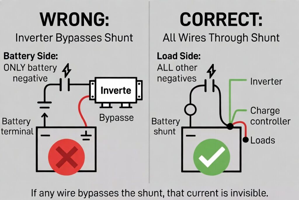
The battery side of the shunt connects ONLY to the battery bank negative terminal. That single wire is the only connection directly to the battery negative. The load side of the shunt connects to ALL other negative wires in the system. This includes the inverter negative, charge controller negative, DC load panel negative, and any accessory that draws or supplies current.
If any wire bypasses the shunt and connects directly to the battery negative, that current is invisible to the monitoring system. The shunt cannot measure what does not pass through it. Invisible current means the SoC calculation drifts further from reality with every charge and discharge cycle. The shunt thinks the battery is fuller than it actually is, which leads to unexpected shutdowns when the battery hits low-voltage cutoff while the display still shows 40 percent.
Battery Monitor Shunt Installation Sequence Step by Step
Step 1: disconnect all positive and negative connections from the battery bank. Step 2: install the shunt battery-side bolt to the battery negative terminal. Step 3: reconnect ALL negative wires to the shunt’s load-side bolt. Step 4: reconnect all positive connections. Step 5: open VictronConnect and configure the shunt with your battery capacity in Ah, battery chemistry (LFP or lead-acid), and charged voltage (14.2V for LFP at 12V). Step 6: verify the display shows correct voltage and zero current with no loads active. For fusing requirements on all connections, see our solar system fusing guide.
The most important step is Step 3. Every single negative wire must move from the battery terminal to the shunt’s load-side bolt. If you miss one wire, that circuit becomes invisible. The inverter negative is the most commonly missed because it uses the thickest cable and is often the first wire installed before the shunt. Check every negative connection twice before powering up. For controller connections, see our charge controller wiring guide.
What the SmartShunt Dashboard Shows and How to Read It
The VictronConnect app displays six readings from the battery monitor shunt in real time. Voltage shows the battery bank voltage. Current shows the flow rate in amps, with positive numbers indicating charging and negative numbers indicating discharging. Power shows the total watts being consumed or generated. State of Charge shows the true remaining capacity as a percentage based on coulomb counting.
Consumed Ah shows how many amp-hours have been used since the last full charge. Time Remaining calculates how many hours of battery life remain at the current discharge rate. The consumed Ah counter resets to zero automatically when the battery reaches the configured charged voltage during a full charge cycle. This self-calibration keeps the SoC calculation accurate over thousands of cycles.
The Rockwood Parasitic Draw Catch
A client in Rockwood noticed his battery bank was dropping 5 percent overnight even though every appliance was turned off. He checked the main disconnect switch and confirmed it was off. His inverter was in standby mode drawing less than 1W. He could not find the source of the overnight drain.
Because he had correctly installed a Victron SmartShunt on the battery negative, the VictronConnect app showed a constant minus 0.8A draw. We started pulling fuses one by one while watching the app’s current reading in real time. When we pulled the stereo circuit fuse, the draw dropped to zero instantly. An old amplifier wired to the always-on 12V bus was drawing 0.8A continuously, which consumed 19.2Ah per day. That is 246Wh of battery capacity drained every 24 hours by a device nobody was using.
It was like a stuck glovebox light in a car. The dome light switch shows off, the headlights are off, but something is draining the battery overnight. Without an ammeter on the circuit, you replace the battery and blame age. The $180 SmartShunt saved him from spending $2,000 on new batteries that would have been drained by the same hidden load. The battery monitor shunt is the ammeter that finds the leak.
The Milton Inverter Bypass Error
A DIYer in Milton installed his SmartShunt correctly on the battery negative terminal. He connected his LED lights and charge controller to the load side of the shunt. The VictronConnect app showed voltage and small current draws accurately. He was satisfied that the system was working correctly.
When he ran his microwave through the 2,000W inverter, the SmartShunt showed no change in current or power draw. A 2,000W load was invisible to the shunt. His inverter’s thick negative cable was bolted directly to the battery negative terminal, bypassing the shunt entirely. The shunt only saw the small loads on its load side. The 2,000W inverter draw was not passing through the shunt and therefore did not exist in the SoC calculation.
This is like a gym member who eats a full meal but does not log it in their calorie tracker. The tracker shows a perfect day. The body tells a different story. Moving the inverter’s negative cable from the battery terminal to the shunt’s load-side bolt fixed the problem instantly. Every negative wire in the system must pass through the battery monitor shunt. No exceptions. No bypasses. One wire to the battery. Everything else to the load side.
Battery Monitor Shunt Verdict and Who Needs One in Ontario
The battery monitor shunt verdict depends on whether your system has built-in monitoring or requires external hardware.
- Portable power station users with Jackery, Bluetti, EcoFlow, or Anker units do not need an external shunt. The monitoring is built into your unit. The app on your phone shows SoC, voltage, and current. No external hardware required.
- RV, van, and boat builders with a custom battery bank need a Victron SmartShunt on the battery negative. Connect VictronConnect via Bluetooth. This tells you whether your alternator is actually charging, whether your fridge is draining overnight, and how many hours of battery remain at your current draw rate. For battery health, see our solar battery lifespan guide.
- Off-grid homeowners and cottage builders need a SmartShunt connected to a Victron Cerbo GX for VRM remote monitoring from your phone anywhere in Ontario. Low battery alerts arrive by notification before the pipes freeze. Temperature compensation via a Victron Battery Sense adjusts SoC calculations for Ontario cold weather. This combination is non-negotiable for any system where the owner is not on-site daily. For ongoing care, see our solar generator maintenance guide.
Frequently Asked Questions
Q: Do I need a shunt for each battery in the bank?
A: No. One shunt handles the entire battery bank as long as it is installed on the main negative line where all current passes through. The shunt measures the total bank current, not individual battery current. For individual battery health monitoring, use a Victron Battery Sense on each battery.
Q: Does the shunt draw power from the battery?
A: Yes, but less than 1mA, which is negligible compared to any other load in the system. The SmartShunt’s own power consumption is less than 0.01Ah per day. This is far less than the capacity you would lose to incorrect SoC guessing without a shunt.
Q: Can a 500A shunt handle a 3,000W inverter?
A: Yes. A 500A shunt handles up to 6,000W at 12V or 24,000W at 48V. A 3,000W inverter at 12V draws 250A, which is half the shunt’s 500A rating. The shunt has more than enough capacity for any residential solar system.
NEC Article 690 covers photovoltaic system battery monitoring and grounding requirements including the installation of current-sensing devices on battery bank conductors. All monitoring equipment must be installed according to manufacturer specifications and local code requirements. Current standards are published at nfpa.org.
CEC Section 64 governs battery monitoring equipment and system grounding requirements for solar installations in Ontario. All battery monitor shunt installations must comply with ESA guidelines for conductor sizing and safe wiring practices. The Electrical Safety Authority (ESA) provides current compliance guidelines at esasafe.com.
This build is engineered within the 48V DC Safety Ceiling. Diagnostic logic is based on 20+ years of technical service experience. All structural and electrical installations must be verified by a Licensed Professional and comply with your Local AHJ. See our legal and safety disclosure for full scope.
About the Author
Robert Bertrand spent 20 years as a service advisor in the automotive industry (Lexus and Nissan), where precision diagnostics, wiring integrity, and documentation standards were non-negotiable. He brings that same technical discipline to GridFree Guide, where he researches, tests, and documents off-grid solar systems for Ontario conditions. Based in Rockwood, Ontario, every article is built on verified specifications, manufacturer data, and the real-world climate constraints of Canadian off-grid living.
As an Amazon Associate I earn from qualifying purchases. This site also contains affiliate links to other products and services. GridFree Guide earns a small commission at no extra cost to you.