
Read the Code and Why You Must Diagnose Inverter Faults Before Replacing Parts
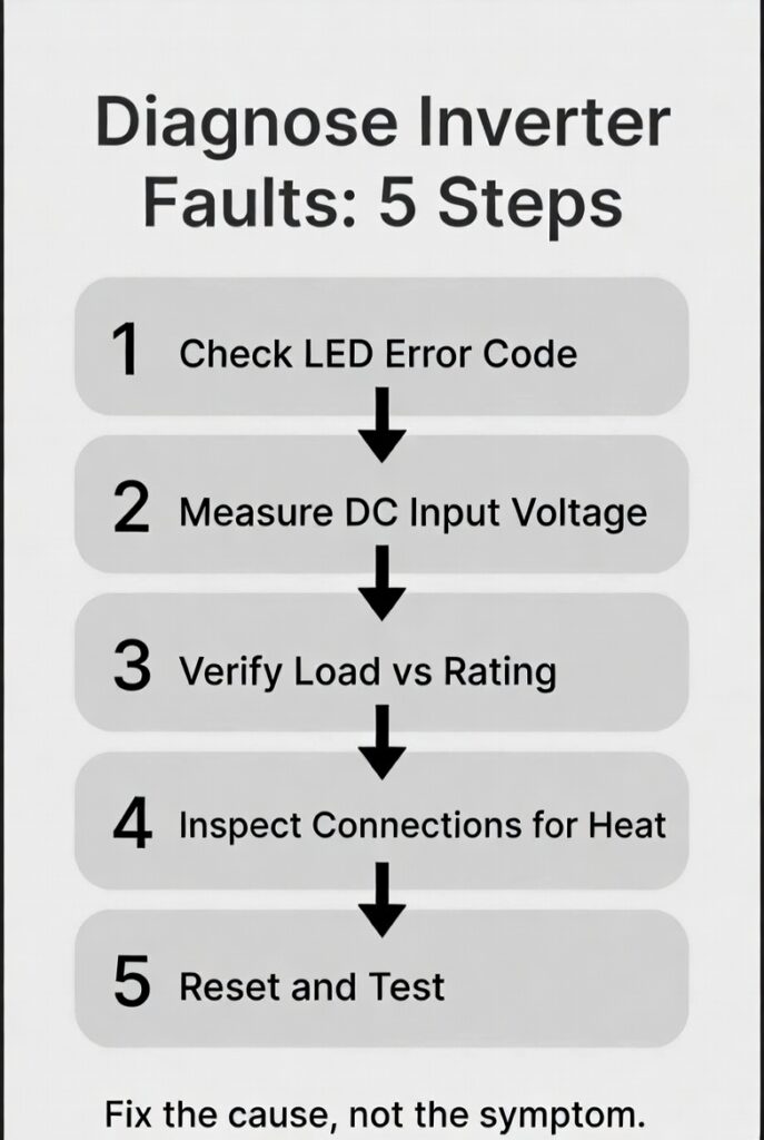
Learning to diagnose inverter faults with a systematic 5-step checklist saves you from replacing a $1,800 unit when the real problem is a $2 fuse or a loose connection you can fix in 10 minutes. The fault light is a symptom, not a diagnosis. Replacing the inverter without checking external causes is called “parts cannoning.” Ninety percent of faults are caused by external issues that cost $0 to $20 to fix.
The breakdown is consistent across every brand and model. Low battery voltage causes 40 percent of inverter faults. Overloaded circuits cause 25 percent. Loose or corroded connections cause 15 percent. Overheating causes 10 percent. Only 10 percent of faults are actual internal inverter failures. The 5-step diagnostic checklist eliminates every external cause before you consider replacing the unit. For the complete wiring architecture, see our off-grid electrical wiring guide.
The Rockwood Systematic Pro
A homeowner in Rockwood saw an intermittent “Low Battery” fault on his Victron MultiPlus-II despite his Victron SmartShunt showing 90 percent SoC. The fault appeared under load and cleared when the load dropped. Instead of replacing the unit, he followed the 5-step diagnostic checklist. He started by measuring voltage at the inverter terminals with a multimeter, not at the battery terminals.
The multimeter showed 46.8V at the inverter terminals while the SmartShunt at the battery showed 52.1V. That 5.3V drop meant a high-resistance connection somewhere between the battery and the inverter. He traced the cables and found a loose positive lug at the busbar with only finger-tight torque. While tightening the lug to spec, he noticed the cable jacket had started to discolour from heat, which meant he caught a potential fire hazard months before it became a crisis.
To diagnose inverter faults correctly, you have to treat the inverter like an Engine Control Unit. If your car will not start, you do not buy a new engine first. You check if there is gas in the tank (battery voltage), check if the starter is jammed (overload), and look for a blown fuse. The inverter is a computer with a big transformer attached. Treat it with the same diagnostic respect you would give a Lexus LS. Total repair cost: $0. Total time: 10 minutes.
The Battery Voltage Check and the Load Verification Steps
Step 1 is measuring DC voltage at the inverter terminals, not the battery terminals. A SmartShunt shows battery voltage. A multimeter at the inverter shows delivered voltage. If there is more than 0.5V difference, you have a high-resistance connection between the battery and the inverter. A 52.1V reading at the battery and a 46.8V reading at the inverter means 5.3V of loss across the cables and connections. For the complete voltage reference, see our battery voltage guide and our solar battery guide.
Step 2 is disconnecting all AC loads. If the fault clears, the problem is overload. Reconnect loads one at a time until the fault returns. The last load connected is the culprit. Common culprits are microwave inrush at 1,500W surge, well pump startup at 1,500W surge, and space heaters at 1,500W continuous. These loads draw 3 to 5 times their rated wattage for the first 1 to 3 seconds.
Step 3 is inspecting every connection between the battery and the inverter. Look for discolouration, melted insulation, warm terminals, or loose lugs. A loose connection creates resistance. Resistance creates heat. Heat creates more resistance. This cycle ends in fire if not caught early. For the complete capacity verification, see our battery capacity test guide.
Common Fault Codes and How to Diagnose Inverter Faults by LED Pattern
| LED/Code Status | Most Common Cause | The Diagnostic Check |
|---|---|---|
| Solid Red LED | Severe Overload | Disconnect AC loads. Reset. |
| Flashing Red (1x) | Low Battery Voltage | Check battery SoC and DC cable connections. |
| Flashing Red (2x) | Over-Temperature | Check fan clearance and ambient room temp. |
| Internal Hum/Buzz | Inductive Load Surge | Verify if a pump or compressor just started. |
| Flashing Yellow | Ground Fault | Check ground connections and GFCI outlets. |
The table covers the 5 most common fault patterns across Victron and most major inverter brands. VictronConnect logs the last 50 faults with timestamps, which shows whether the fault is intermittent or persistent. An intermittent fault that appears only under load points to connections or overload. A persistent fault at idle points to internal failure.
Only after eliminating all 5 external causes should you consider warranty replacement. If the VictronConnect log shows the same error code every 30 seconds at idle with no load connected and all connections verified tight, that is a genuine internal failure. Everything else is external. For the complete charging parameter check, see our charging stages guide.
The Milton Parts Cannon and the Hard Reset Protocol
A DIYer in Milton saw a “Fault” light on his budget 3,000W inverter. He did not read the fault code. He did not check battery voltage. He did not inspect connections. He ordered a new $1,800 Victron MultiPlus-II as a replacement because he assumed the budget inverter had failed.
The new MultiPlus-II threw the exact same fault code 10 minutes after installation. The problem was not the inverter. A $2 blade fuse on his DC distribution block had blown from a short circuit caused by his microwave’s inrush current. Two inverters, same fault, same cause. The fuse was the problem from the beginning.
Because he “self-diagnosed” by replacing parts, the original seller refused the return on the first inverter since it had been installed and powered on. He was stuck with a $1,800 paperweight and a $2 fuse that needed replacing. Learning to diagnose inverter faults systematically would have found the blown fuse in step 2 of the checklist. The rule is simple: never replace the unit until you have eliminated every external cause first.
The hard reset protocol follows a specific sequence. Disconnect DC first using the battery disconnect or breaker. Disconnect all AC loads. Wait 60 seconds for internal capacitors to discharge. Reconnect DC first and wait for the inverter to complete its boot sequence, which takes 10 to 15 seconds on a MultiPlus-II. Reconnect AC loads one at a time. If the fault returns on the first load, that load is the problem, not the inverter.
Frequently Asked Questions
Q: Why does my inverter keep tripping on overload?
A: The most common cause is inductive load startup surge from motors like well pumps, compressors, and washing machines which draw 3 to 5 times their rated wattage for the first 1 to 3 seconds. A 1,500W inverter cannot handle a well pump that surges to 3,000W on startup even though the running load is only 800W. The solution is either upgrading to a larger inverter or adding a soft starter to the motor.
Q: Should I replace my inverter if it keeps showing fault codes?
A: Not until you have eliminated all external causes using the 5-step diagnostic checklist because 90 percent of inverter faults are caused by low battery voltage, loose connections, overloaded circuits, or overheating. Replacing the inverter without fixing the root cause means the new unit will throw the same fault code. Check voltage at the inverter terminals and inspect every connection before ordering a replacement.
Q: How do I read fault codes on a Victron MultiPlus-II?
A: The front panel LEDs show real-time status with red flashing patterns indicating specific faults. The VictronConnect app connected via Bluetooth or VE.Bus shows detailed error codes with timestamps and stores the last 50 fault events. Checking the error log first tells you whether the fault is intermittent under load or persistent at idle, which determines whether the cause is external or internal.
NEC Article 705 covers inverter installation and fault protection requirements including overcurrent protection, grounding, and disconnect standards for residential solar systems. All inverter installations must comply with applicable fault protection and disconnection standards. Current standards are published at nfpa.org.
CEC Section 64 governs inverter installation and fault protection requirements in Ontario including disconnect placement, grounding, and overcurrent protection standards. All permanently installed inverters require ESA-compliant installation and inspection. The Electrical Safety Authority (ESA) provides current compliance guidelines at esasafe.com.
This build is engineered within the 48V DC Safety Ceiling. Diagnostic logic is based on 20+ years of technical service experience. All structural and electrical installations must be verified by a Licensed Professional and comply with your Local AHJ. See our legal and safety disclosure for full scope.
About the Author
Robert Bertrand spent 20 years as a service advisor in the automotive industry (Lexus and Nissan), where precision diagnostics, wiring integrity, and documentation standards were non-negotiable. He brings that same technical discipline to GridFree Guide, where he researches, tests, and documents off-grid solar systems for Ontario conditions. Based in Rockwood, Ontario, every article is built on verified specifications, manufacturer data, and the real-world climate constraints of Canadian off-grid living.
As an Amazon Associate I earn from qualifying purchases. This site also contains affiliate links to other products and services. GridFree Guide earns a small commission at no extra cost to you.