
Understanding the Bulk Absorption Float Algorithm and Why Defaults Destroy LFP
Understanding the bulk absorption float charging algorithm is the difference between a battery bank that lasts 10 years and one that degrades in 10 months because wrong voltage targets silently destroy cells every charge cycle. Most charge controllers ship with AGM defaults. These defaults push 0.2V too high on absorption and 0.3V too high on float for LFP batteries. That small voltage difference destroys cells over 8 to 12 months of daily cycling.
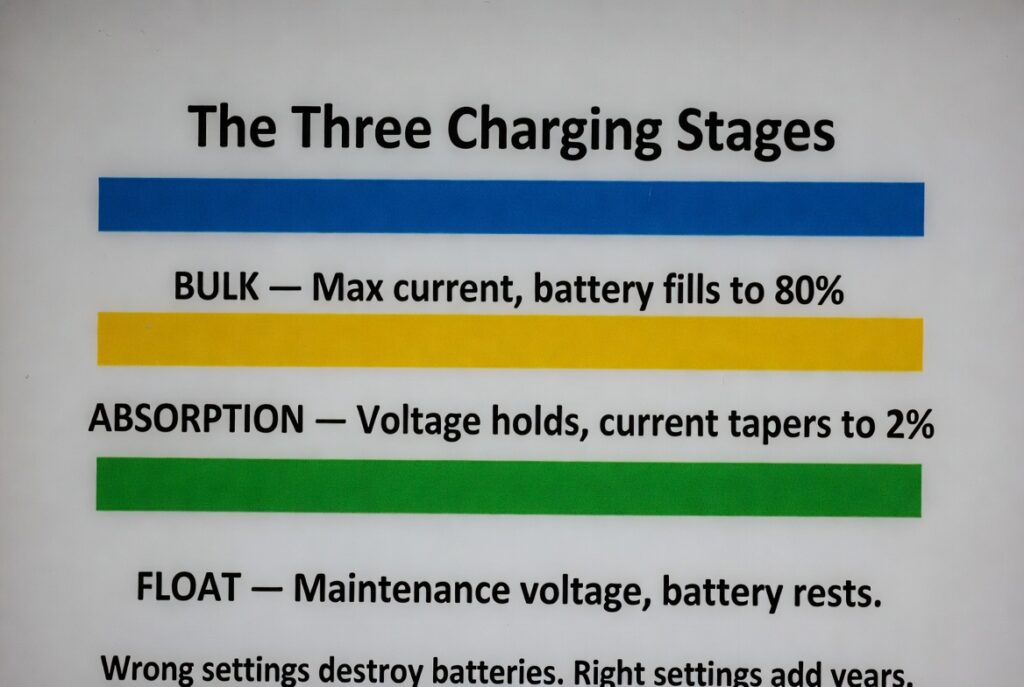
The three stages each have a specific job. Bulk fills the battery quickly to 80 percent SoC using maximum available current. Absorption finishes the charge precisely to 100 percent by holding voltage constant while current tapers. Float maintains the charge at a lower voltage without stressing the cells. For the complete battery decision map, see our solar battery guide. For the full charging protocol, see our battery charging guide.
The Rockwood Precision LFP Calibration
A homeowner in Rockwood configured his Victron MPPT 100/50 with custom LFP bulk absorption float parameters using the VictronConnect app. He set absorption voltage to 14.2V at 12V (56.8V at 48V). He set float voltage to 13.5V at 12V (54.0V at 48V). He set the tail current threshold to 2 percent of bank capacity, which triggers the transition from absorption to float automatically.
By dropping the absorption voltage from the AGM default of 14.4V to the LFP target of 14.2V, he reduced heat generation during the final 5 percent of each charge cycle. This lower heat protected the battery’s internal BMS from nuisance over-voltage disconnect trips that plague systems running AGM defaults on LFP. After 3 years of daily cycling, his Victron SmartShunt confirms the bank still holds 98 percent of its original rated capacity. The 0.2V difference between correct and incorrect absorption voltage is worth 7+ years of additional battery life.
Managing bulk absorption float stages is exactly like a three-stage paint correction on a vehicle. Bulk is the heavy compounding. You move fast to remove 80 percent of the defects. Absorption is the fine polishing. You slow down and use precision to achieve a perfect finish. Float is the final wax that protects the work without stripping anything away. Using AGM voltage settings on LFP is like using heavy-grit sandpaper for the final wax. You ruin the finish before you realize the damage.
The Bulk Stage and Absorption Stage Explained for Ontario Solar Systems
The bulk stage is where the controller pushes maximum available current into the battery. Voltage rises steadily until the battery reaches the absorption voltage target. For LFP at 12V, this target is 14.2V. For AGM at 12V, it is 14.4V. The bulk stage handles 80 percent of the charging work in approximately 60 to 70 percent of the total charge time. For the complete programming guide, see our charge controller settings guide.
In the absorption stage, voltage holds constant at the target while current tapers as the battery approaches full charge. The transition to float occurs when current drops to the tail current threshold, typically 2 percent of the bank’s Ah rating. A 100Ah bank transitions when current drops to 2A. A 400Ah bank transitions at 8A. For the step-by-step programming instructions, see our program controller for LFP guide.
The difference between 14.2V and 14.4V is only 0.2V but it determines whether each charge cycle adds life or removes it. LFP chemistry reaches full charge at 14.2V. Pushing to 14.4V creates excess heat and voltage stress on the cell chemistry. Every single charge cycle at 14.4V instead of 14.2V shortens the battery’s total cycle life. Over 365 days of daily cycling, that is 365 instances of excess voltage applied to cells that did not need it.
The Float Stage and Why LFP Needs Different Bulk Absorption Float Targets Than AGM
The float stage drops voltage to a maintenance level after absorption completes. For AGM, float is 13.6V at 12V because AGM has higher self-discharge at 5 to 10 percent per month. For LFP, float is 13.5V or even disabled entirely because LFP self-discharge is less than 2 percent per month. Many Victron users disable float entirely for LFP and configure a rebulk voltage threshold that restarts charging only when voltage drops below 13.0V.
| Setting | LFP (12V) | LFP (48V) | AGM (12V) | AGM (48V) |
|---|---|---|---|---|
| Absorption Voltage | 14.2V | 56.8V | 14.4V | 57.6V |
| Float Voltage | 13.5V | 54.0V | 13.6V | 54.4V |
| Tail Current | 2% of Ah | 2% of Ah | 3% of Ah | 3% of Ah |
| Float Duration | Minimal or disabled | Minimal or disabled | Continuous | Continuous |
| Self-Discharge/Month | Less than 2% | Less than 2% | 5-10% | 5-10% |
The table above shows why the same controller settings cannot serve both chemistries. The 0.2V absorption difference is the critical number. The float difference matters less for LFP because many builders disable it entirely. The self-discharge rate explains why AGM needs continuous float maintenance while LFP does not. For the complete voltage analysis, see our battery voltage guide.
The Milton AGM Default Trap
A DIYer in Milton installed a $3,800 LFP bank but left the charge controller on the factory AGM preset. The AGM preset pushed 14.4V absorption for 2 hours every day regardless of the battery’s actual needs. The AGM float voltage of 13.8V kept the LFP cells under constant voltage stress. He did not check the bulk absorption float settings because the controller “worked” out of the box.
Within 8 months, the cells showed visible swelling from persistent overcharging. The total runtime dropped by 30 percent because the electrolyte chemistry was degrading from the 0.2V excess absorption voltage applied daily. The high float voltage of 13.8V (versus the correct 13.5V for LFP) meant the lithium ions were constantly under stress between charge cycles. The BMS logged 247 over-voltage warnings in 8 months but the owner never checked the app.
A $3,800 LFP bank degraded to 70 percent capacity in 8 months because of a 0.2V setting error. The correct bulk absorption float configuration takes 5 minutes in the VictronConnect app. The correct absorption voltage for LFP at 12V is 14.2V, not 14.4V. The correct float voltage for LFP at 12V is 13.5V, not 13.8V. These two numbers are the difference between 3,000 cycles and 300 cycles on the same cells.
Frequently Asked Questions
Q: What are the correct LFP charging voltages?
A: Absorption at 14.2V for 12V systems or 56.8V for 48V systems. Float at 13.5V for 12V or 54.0V for 48V. Tail current at 2 percent of bank Ah rating, which is 2A for a 100Ah bank. These three settings must be programmed manually because most controllers ship with AGM defaults.
Q: Can I leave my charge controller on AGM settings for LFP?
A: No, because AGM absorption voltage of 14.4V pushes LFP cells 0.2V above their safe charging threshold every cycle. This persistent overcharging causes cell swelling and 30 percent capacity loss within 8 to 12 months. Changing the settings takes 5 minutes in the VictronConnect app and adds 7+ years to the battery’s service life.
Q: Does LFP need a float stage?
A: LFP needs minimal or no float because its self-discharge rate is less than 2 percent per month compared to 5 to 10 percent for AGM. Many Victron users disable float entirely and configure a rebulk voltage threshold that restarts charging only when voltage drops below 13.0V. This approach eliminates the constant voltage stress that shortens LFP cell life.
NEC Article 480 covers battery charging system safety requirements including proper voltage regulation, overcurrent protection, and prevention of overcharging conditions. All charge controller settings must comply with battery manufacturer specifications. Current standards are published at nfpa.org.
CEC Section 64 governs battery charging system installation and configuration requirements in Ontario. All charge controllers must be programmed to match the installed battery chemistry per ESA guidelines. The Electrical Safety Authority (ESA) provides current compliance guidelines at esasafe.com.
This build is engineered within the 48V DC Safety Ceiling. Diagnostic logic is based on 20+ years of technical service experience. All structural and electrical installations must be verified by a Licensed Professional and comply with your Local AHJ. See our legal and safety disclosure for full scope.
About the Author
Robert Bertrand spent 20 years as a service advisor in the automotive industry (Lexus and Nissan), where precision diagnostics, wiring integrity, and documentation standards were non-negotiable. He brings that same technical discipline to GridFree Guide, where he researches, tests, and documents off-grid solar systems for Ontario conditions. Based in Rockwood, Ontario, every article is built on verified specifications, manufacturer data, and the real-world climate constraints of Canadian off-grid living.
As an Amazon Associate I earn from qualifying purchases. This site also contains affiliate links to other products and services. GridFree Guide earns a small commission at no extra cost to you.