
How to Wire Solar Charge Controller Units and Why the Connection Sequence Is Non-Negotiable
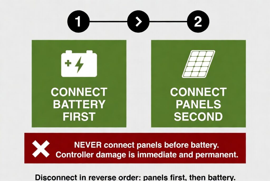
Learning how to wire solar charge controller units correctly requires following a strict connection sequence because reversing the order destroys the controller. A charge controller is the regulator between your solar panels and your battery bank. It manages the charging voltage and current to protect the battery from overcharging. The controller must detect the battery voltage before it can safely process incoming PV power.
The auto-detect feature on Victron controllers reads battery voltage during initialization to set 12V, 24V, or 48V operation. Without the battery connected first, the controller has no voltage reference. Connecting panels to an uninitialized controller sends unregulated PV voltage into circuitry that is not ready to manage it. The result is permanent damage to the MPPT tracking components within seconds.
This article covers the battery-first connection sequence, terminal specifications, fusing requirements, and the Ontario cold-weather VOC calculation that most guides skip. Every step references the wire gauge, fusing, and voltage selection guides that form the foundation of the Wiring and Electrical category. For a broader overview, see our solar generator Ontario guide.
The Battery-First Connection Sequence Step by Step
Step 1: connect battery positive and negative to the controller battery terminals. The controller powers on, the LED indicates battery detected, and the unit auto-detects the system voltage. Step 2: connect solar panel positive and negative to the controller PV terminals. The controller begins MPPT tracking and the charge indicator shows active charging. This sequence ensures the controller has a load to absorb the incoming PV energy from the moment the panels connect.
Fuse the battery connection within 7 to 12 inches of the battery positive terminal per CEC requirements. Use a DC-rated breaker on the PV positive line as both overcurrent protection and a disconnect switch. The PV breaker is critical because it allows you to safely cut solar input before disconnecting the battery during maintenance. Disconnect sequence is reversed: flip the PV breaker first, then disconnect the battery. For fuse sizing details, see our solar system fusing guide.
How to Wire Solar Charge Controller Terminals and Connection Specifications
Every connection point on the controller has specific wire gauge, fusing, and termination requirements. Using the wrong wire gauge starves the controller of power or overheats the conductor. Using the wrong termination method creates loose connections that generate heat over time. The table below covers all four connection points.
| Connection | Wire Spec | Fusing Requirement |
|---|---|---|
| Battery +/- | Gauge per wire chart, sized for max charge current | Fuse within 7-12 inches of battery |
| PV +/- | UV-rated 10 AWG to 8 AWG solar cable | DC breaker or inline fuse |
| Ground | 6 AWG bare copper to chassis and ground rod | No fuse on ground conductor |
| Terminals | Ferrule connectors on stranded wire | Torque to manufacturer spec |
Use ferrule connectors crimped onto stranded wire for all screw terminals. Do not tin stranded wire with solder for screw terminals. Tinned wire cold-flows under screw pressure and loosens over time, creating a high-resistance connection that generates heat. A WBHome crimper and ferrule set costs under $30 and handles every terminal on the controller. For wire gauge selection, see our wire gauge solar panels guide. For voltage selection, see our 12V vs 24V vs 48V guide.
The Ontario Cold-Weather VOC Calculation and Why January Kills Controllers
Solar panel open-circuit voltage increases as cell temperature decreases. The temperature coefficient for VOC is approximately minus 0.35 percent per degree C below 25 degrees C, which is the Standard Test Condition temperature. On a minus 25 degrees C Ontario January morning, the delta from STC is 50 degrees C. The VOC increase is 50 x 0.35 percent = 17.5 percent above the rated STC specification.
Two panels at 41V each wired in series produce 82V at STC. At minus 25 degrees C, the cold-weather VOC is 82V x 1.175 = 96.4V. A controller rated for 100V max input has only 3.6V of margin on that January morning. One more panel in the string would push the voltage to 144.5V and destroy the controller instantly. Always calculate cold-weather VOC before finalizing series string length. Leave a minimum 20 percent margin between your calculated cold-weather VOC and the controller’s maximum input voltage.
The Rockwood Battery-First Save
A DIYer in Rockwood was about to connect his 400W solar array to a Victron MPPT 100/30 before connecting his battery bank. He had the MC4 connectors in hand and the panels were producing full power in the afternoon sun. His 200Ah LFP battery was still in the box, unopened. He planned to connect the battery after the panels because he wanted to test the solar input first.
The Victron MPPT 100/30 is an auto-detect unit that reads battery voltage during initialization to determine whether it is charging a 12V or 24V bank. Without the battery connected, the controller has no voltage reference and cannot set its operating parameters. If he had connected the panels first, the 82V open-circuit voltage from the array would have hit the controller’s input without any load to absorb it. The internal capacitors would have charged to the full array VOC with no regulation, likely damaging the MPPT tracking circuitry.
Connecting panels before the battery is like starting an engine before checking the oil level. The pump runs but there is no fluid in the system to protect the moving parts. The battery is the load that gives the controller somewhere to send the energy. Without it, the controller is running dry. Following the battery-first sequence saved him from replacing a $250 controller before his system ever produced its first watt.
The Milton Battery Swap Disaster
A client in Milton needed to swap a dead battery cell in his 24V bank. His system was running a 600W array through a Victron MPPT 100/50. He disconnected the battery terminals from the controller while the panels were still connected and producing approximately 30A of current in full afternoon sun. He did not flip the PV breaker first.
With the battery disconnected, the controller had nowhere to send the 30A of incoming current. The internal capacitors absorbed the initial surge but could not sustain it. The controller overloaded internally within seconds. The unit emitted a burning smell and shut down permanently. He destroyed a $350 controller because he did not disconnect the panels before disconnecting the battery.
Disconnecting the battery while the panels are producing is like disconnecting a car battery while the alternator is at full output. Without the battery to absorb the voltage, the alternator’s output spikes and fries every connected electronic module. The charge controller needs the battery as a voltage buffer at all times when PV power is flowing. The correct sequence is: disconnect panels first, then disconnect battery. A $10 DC breaker on the PV line would have prevented this $350 failure.
How to Wire Solar Charge Controller Verdict and Which Controller Fits Your Build
This wire solar charge controller verdict splits into three profiles based on system size and Ontario cold-weather requirements.
- Van and RV builders with systems up to 400W should use a Victron MPPT 100/30 at 30A max charge current. The 100V max input handles two panels in series with cold-weather margin at minus 25 degrees C. Keep all cable runs under 15 feet and use 10 AWG solar cable for PV runs.
- Cabin and cottage builders with 400W to 700W arrays should use a Victron MPPT 100/50 at 50A max charge current. The 100V max input handles up to 700W at 12V or 1,400W at 24V. Use a Blue Sea ANL fuse block for the battery connection. Calculate cold-weather VOC to verify the series string stays under 100V at minus 25 degrees C.
- Professional off-grid builders with arrays above 1,000W should use a controller with 150V or higher max input rating for Ontario cold-weather margin. Wire panels in series strings that stay under the max input voltage at minus 25 degrees C with 20 percent margin. Use ferrule connectors on all stranded wire and torque all terminals to manufacturer spec. For annual terminal inspection, see our solar generator maintenance guide.
Frequently Asked Questions
Q: What happens if I connect panels before the battery?
A: The controller receives unregulated PV voltage without a load to absorb it. The internal capacitors charge to the full array open-circuit voltage, which can damage the MPPT tracking circuitry. Always connect the battery first so the controller initializes and sets its operating parameters before receiving PV input.
Q: Can I use the load output for my fridge?
A: No. Most load outputs are limited to 10A to 20A, which is insufficient for a fridge compressor startup surge. Use the load output for small DC loads like LED lights or vent fans only. Connect your fridge to the battery through an inverter, not through the controller load output.
Q: Should I tin stranded wire before inserting it in screw terminals?
A: No. Tinned solder on stranded wire cold-flows under screw pressure and loosens over time, creating a high-resistance connection. Use ferrule connectors crimped onto the stranded wire instead. Ferrules provide a solid contact surface that maintains torque and does not cold-flow.
NEC Article 690 covers photovoltaic system charge controller installation requirements including PV circuit overcurrent protection and conductor termination standards. All connections must be properly fused and terminated per manufacturer specifications. Current standards are published at nfpa.org.
CEC Section 64 governs charge controller installation and PV circuit safety requirements in Ontario. All battery connections must include overcurrent protection within 7 to 12 inches of the battery terminal. The Electrical Safety Authority (ESA) provides current compliance guidelines and installation inspection resources at esasafe.com.
This build is engineered within the 48V DC Safety Ceiling. Diagnostic logic is based on 20+ years of technical service experience. All structural and electrical installations must be verified by a Licensed Professional and comply with your Local AHJ. See our legal and safety disclosure for full scope.
About the Author
Robert Bertrand spent 20 years as a service advisor in the automotive industry (Lexus and Nissan), where precision diagnostics, wiring integrity, and documentation standards were non-negotiable. He brings that same technical discipline to GridFree Guide, where he researches, tests, and documents off-grid solar systems for Ontario conditions. Based in Rockwood, Ontario, every article is built on verified specifications, manufacturer data, and the real-world climate constraints of Canadian off-grid living.
As an Amazon Associate I earn from qualifying purchases. This site also contains affiliate links to other products and services. GridFree Guide earns a small commission at no extra cost to you.